| RO Unit Components: Basic Assembly | ||||||
| Page 5 of 7 | Pages: 1 . 2 . 3 . 4 . 5 . 6 . 7 | |||||
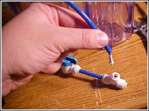 Photo 14: On other RO units the flow restrictor is either inline (looks like a cylinder with fittings on either end) or in the waste water fitting of the membrane housing.
Here's a flow restrictor being installed in the flush assembly. Note the black "tail" goes in the direction of the water flow. Here's a finished flush assembly. It is a simple bypass valve. Turning the blue handle on the ball valve bypasses the flow restrictor that is in the arched tube. The faster flow of water carries away all contaminants on the surface of the membrane. 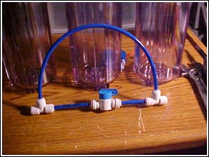 Photo 15: Membranes catch magnesium and calcium at their surface. Over time, a build-up similar to hard water crust on an aquarium forms. Once this gets too thick the membrane stops functioning and has to be replaced. Operating the flush valve for several minutes prevents this from happening. This maintenance step should be performed weekly to daily depending on your feed water conditions.
High quality 1/4" tubing is then used to connect all the fittings on the unit in proper sequence. 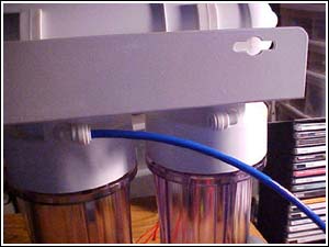 Photo 16: Here the product (filtered water) end of the membrane housing is connected to what will be the DI stage of the unit. 180 degree rotatable fittings are again used.
more... |
 |
|||||
| About Us :: Message Board :: Chat | |||||
| Library :: Photo Gallery :: Links & Resources :: Breeders & Sponsors :: Merchandise | |||||
| Website designed by: EthanCote.com | © 2001-2004, SimplyDiscus.com. All Rights Reserved. | ||||