
 |
||||||||||||
 |
||||||||||||
| RO Units: Parts and Their Functions | ||||||
| Page 4 of 9 | Pages: 1 . 2 . 3 . 4 . 5 . 6 . 7 . 8 . 9 | |||||
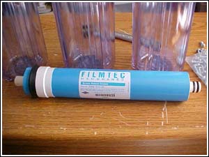 Photo 12: This particular one is a Dow Brand FilmtecTM membrane and is rated for 100 gallons per day. The rating is based on set feed water conditions of: 77 degrees Fahrenheit, 50 PSI, pH of 8.0 and 200 PPM total dissolved solids. If your feed water is lower temperature and pressure or higher pH/TDS you will get less water per day than it is rated for.
Reverse Osmosis membranes are made of a synthetic polymer that has atomic sized holes throughout its surface. The pressure of the incoming feed water forces the water molecules through the membrane while trapping the various ionic contaminates on the surface where they are flushed away by the reject or "waste" water. This particular method of removal is called "cross flow filtration." Reverse osmosis units operate slowly and are not particularly efficient. At rated feed water values, they will reject 4 to 4.5 gallons of water per gallon of filtered water ("permiate" or "product" water). Increasing temperature and pressure of the feed water will increase the efficiency of the unit and will decrease the waste or reject water. CAUTION: Feed water temperatures above 115 degrees F. will destroy the membrane as will pressures above 125 PSI. 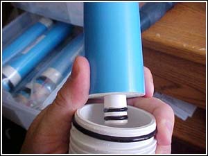 Photo 13: The membrane is inserted into its housing with the two "O" rings on the right side first.
It is very important to lubricate the "O" rings on the membrane prior to insertion into the housing. If this is not done, they may twist or be dislodged during installation and the membrane will not work properly. A good quality silicone gasket lubricant is used. 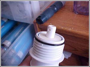 Photo 14: This picture shows the membrane almost all the way inserted. The end cap will then be screwed on to seat the membrane completely.
As I mentioned in a previous thread, the two holes in the tailpiece of the membrane are to assist in removing it for replacement. A piece of wire is threaded through them and used to extract the membrane from the housing. 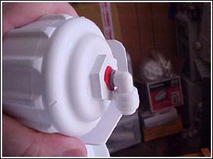 Photo 15: This is a close-up of the membrane housing cap. It only has one connector on it, this is the feed water inlet. Notice the 180 degree rotatable John Guest fitting, this is provided for ease of removal and installation of the cap. Many manufacturers will use cheap compression fittings on the membrane housing, even though it needs to be removed for servicing periodically.
more... |
 |
|||||
| About Us :: Message Board :: Chat | |||||
| Library :: Photo Gallery :: Links & Resources :: Breeders & Sponsors :: Merchandise | |||||
| Website designed by: EthanCote.com | © 2001-2004, SimplyDiscus.com. All Rights Reserved. | ||||