| RO Units: Parts and Their Functions | ||||||
| Page 9 of 9 | Pages: 1 . 2 . 3 . 4 . 5 . 6 . 7 . 8 . 9 | |||||
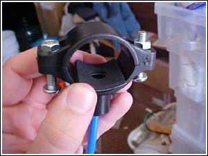 Photo 30: Here is the other end of the system, the waste saddle. This is used for attaching the waste line to a drain pipe. A small hole is drilled in the pipe and the saddle clamps around it. The saddle is equipped with another John Guest fitting for ease of installation. The saddle should be attached to the vertical tailpiece of the drainpipe NOT the horizontal pipe after the trap.
Note the gasket, this is vital to preventing leaks and has double stick tape on it to hold it in place. 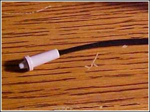 Photo 31: Attached to the waste line is a flush valve that contains a flow restrictor. The flow restrictor provides the back pressure needed by the membrane to force water through it.
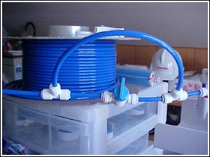 Photo 32: Here is the flush valve assembly. The flow restrictor is located in the "T" fitting on the right. The ball valve in the center, when opened, bypasses the restrictor and provides the high flow flush to the membrane surface. Any contaminants are carried away by the water flow and go down the drain.
The waste saddle is off-screen to the left and the membrane housing is off to the right. 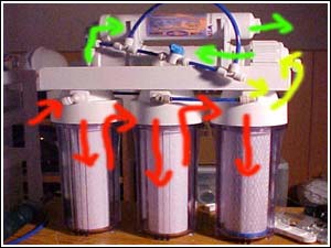 Photo 33: Last but not least, here is a picture of the complete unit. The water feed enters from the fitting on the lower left can and the end product exits from the upper right post filter.
In the horrible Photoshop job I did, the red arrows are feed water with chlorine, the yellow arrows are pre-filtered dechlorinated water and the green arrows are product water (RO filtered). Notice the yellow arrow coming from the waste port via the flush assembly. This water is pure, filtered and dechlorinated water that is only slightly higher in TDS than the feed water. Perfect for growing out young discus. |
 |
|||||
| About Us :: Message Board :: Chat | |||||
| Library :: Photo Gallery :: Links & Resources :: Breeders & Sponsors :: Merchandise | |||||
| Website designed by: EthanCote.com | © 2001-2004, SimplyDiscus.com. All Rights Reserved. | ||||